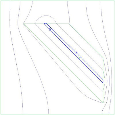
As described in Part 1 and Part 2 of this series, Drain/Fracture elements are useful internal boundaries for easily modeling a variety of hydrologic features including collector trenches, interconnected ponds, and transmissive fracture or fault zones.
This example will demonstrate the use of a drain/fracture line element to represent a zone of more transmissive fractured or faulted rock within a lower permeability bedrock aquifer.
Discrete Fractures and Fracture Zones
In areas with discrete water-bearing fractures, drain elements can be incorporated into an AnAqSim model to direct flow along the higher conductance fracture(s). This capability can be useful when looking at groundwater contours and drawdown; however, particle pathlines cannot be tracked through drain/fracture elements, making interpretation of groundwater flow paths difficult, especially when multiple drain/fracture elements are combined.
To address this pathline issue, the use of separate
fractured domains with anisotropy (different K1_horizontal and K2_horizontal
values and an Angle_K1_to_x_axis aligned with the fracture strike) is
recommended when using particle pathline tracing to evaluate model results is
important. As shown in the examples below, the drawdown caused by pumping
within a fractured region represented by discrete fractures is nearly identical
to the drawdown caused by pumping within a fractured region represented by an
anisotropic domain with representative bulk hydraulic conductivities along
strike and perpendicular to strike (Fig 1 and Fig 2).
 |
Fig 1. Drawdown caused by extraction well located within a
fractured region represented by discrete fractures |
 |
Fig 2. Drawdown caused by extraction well located within the
equivalent anisotropic porous media fractured region |
While the two fractured zone representations both provide similar drawdown plots, they do not produce equivalent particle pathlines to the pumping well located within the fractured region. Pathlines within the equivalent anisotropic porous media agree with the flow of groundwater, predominantly along strike within fractures (Fig 4), while the pathlines tracked from the well located within the discrete fractures appear to flow across strike rather than along it (Fig 3). This is because pathlines that intercept the drain/fracture elements are terminated, so only pathlines that aren’t captured by the drains are tracked perpendicular to the hydraulic gradient.
 |
Fig 3. Pathlines tracked to an extraction well located
within a fractured region represented by discrete fractures |
 |
Fig 4. Pathlines tracked to an extraction well located
within the equivalent anisotropic porous media fractured region |
Summary
Drain/fracture elements can easily produce hydraulic head contours resulting from discrete fractures, pipes, or karst zones located within an aquifer and can effectively represent drawdown resulting from pumping near those drain/fracture elements. If capture zones are desired, drain/fracture elements are not the right choice because the particles are not tracked along the line elements. Instead, representative anisotropic domains may be more appropriate for representing capture zones. The discrete drain/fracture elements can still play a role in developing the representative anisotropic domain if the number, aperture (width), and hydraulic conductivity of the fractures is approximately known. This will allow a model with an anisotropic domain to be fit to the discrete fracture model (by adjusting K1_horizontal, K2_horizontal, and Angle_K1_to_x_axis in the fracture domain window).
Tips and Tricks
- Use more closely spaced nodes near the end of drain/fracture line elements where the boundary condition is changing rapidly if head contours are not smooth.
- Using equations within excel can be useful to quickly set up multiple line boundaries that are aligned parallel to each other.
The models used in the above examples are available in this zipped file. The above examples require the full version of AnAqSim to solve. AnAqSim is available from Fitts Geosolutions.
